
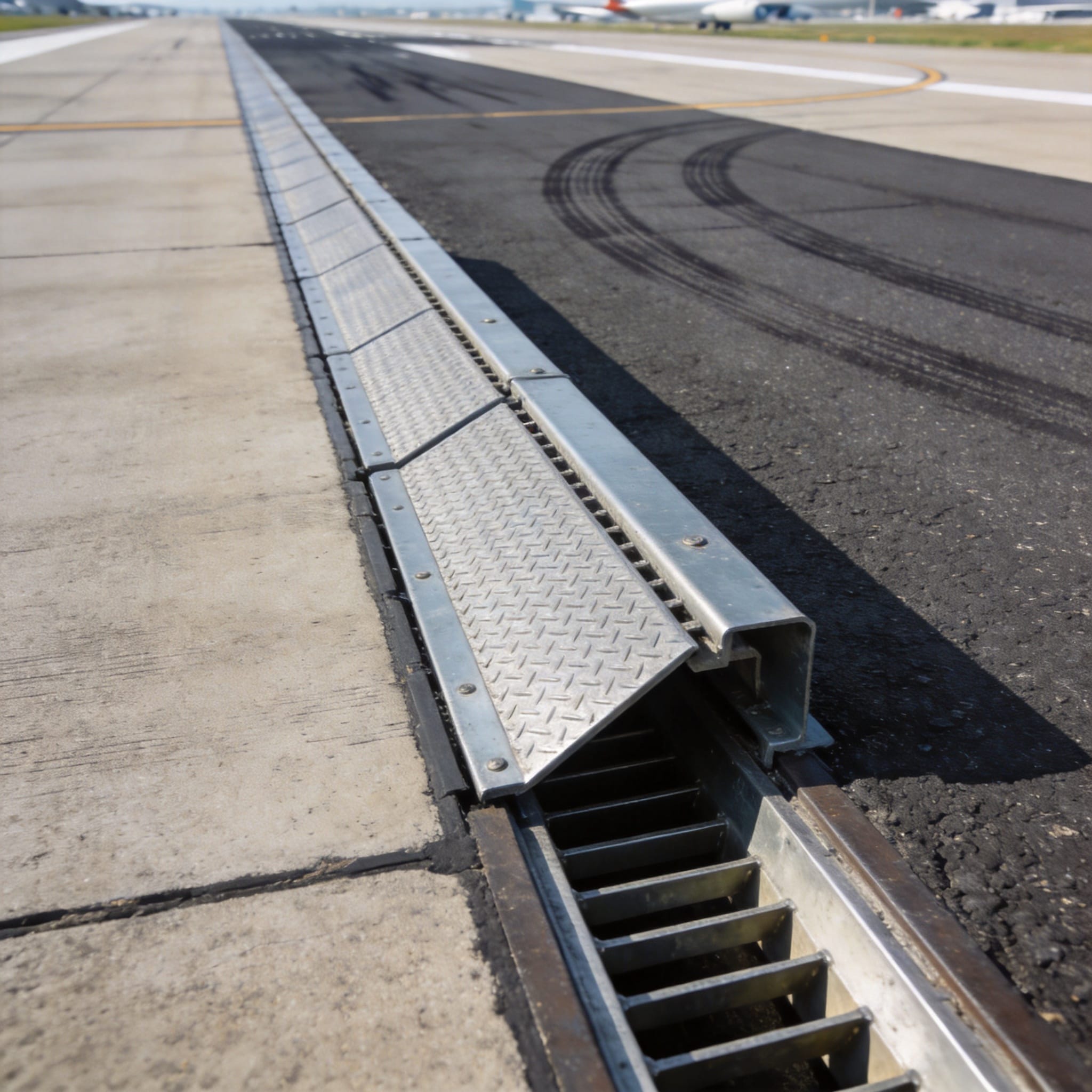
Airport pavements are among the most demanding civil engineering surfaces on earth. While the asphalt and concrete layers handle the primary stresses, the covers and drains for airport pavements represent critical weak points that require special designs for aircraft loads. A failure in a trench drain or a manhole cover on a runway is not a maintenance nuisance; it is a potential catastrophic safety hazard. In this guide, I will break down the specific engineering principles, load classifications, and testing protocols required to keep these components safe under the immense forces of landing gear.
Understanding the Load Environment: Why Airports Differ from Highways
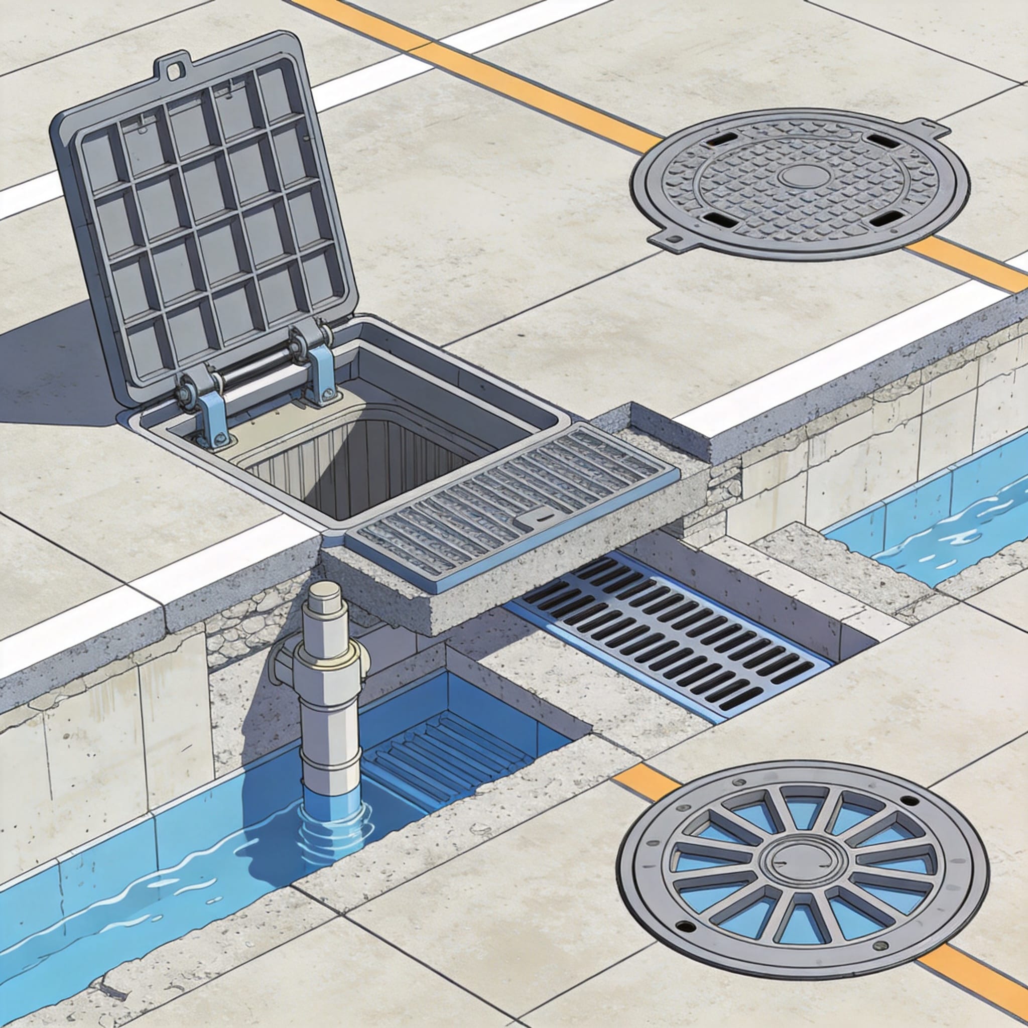
The static weight of a fully loaded commercial airliner is only part of the story. The dynamic impact during landing, known as the “hard landing” scenario, applies a multiplier effect to the static load. For instance, a Boeing 747-400 has a maximum takeoff weight of approximately 396,890 kg, but the load on a single landing gear strut during touchdown can momentarily exceed twice the static load. This sudden application of force is known as impact loading, and it is the primary reason standard highway covers fail on airfields.
Furthermore, the tire pressure of aircraft is significantly higher than that of trucks. Modern aircraft tires operate at pressures ranging from 1.0 to 1.5 MPa (145 to 220 psi), compared to roughly 0.7 MPa for heavy trucks. This high pressure concentrates the load into a very small footprint, creating extreme localized stress on any cover or grate in the pavement. The pass-to-coverage ratio is also critical; aircraft tend to follow the same centerline path, concentrating wear and fatigue on specific drainage points rather than distributing it across a wide lane.
In my 15 years of testing composite materials for infrastructure, I have observed that fatigue failure¡ªnot static overload¡ªis the most common cause of cover failure in airport environments. A cover might withstand a single static load test easily, but after 100,000 cycles of taxiing aircraft, the material may develop micro-cracks that propagate into structural failure. Therefore, any design for airport use must prioritize fatigue resistance over simple ultimate strength.
The Role of Subgrade Support
The performance of a cover or drain is intrinsically linked to the support provided by the surrounding pavement and subgrade. If the pavement settles, the cover will rock or pop out of its frame under load. This is why the design of the casting frame is just as important as the cover itself. The frame must be designed to transfer the load effectively to the pavement structure, not just sit on top of it.
Engineers must account for the “bending moment” transferred to the frame edges. In airport designs, we typically specify a deeper frame with a wider flange to spread the load over a larger area of the pavement. This reduces the pressure on the concrete or asphalt edge, preventing the spalling and cracking that leads to premature failure.
Key Design Standards for Airport Drainage and Covers
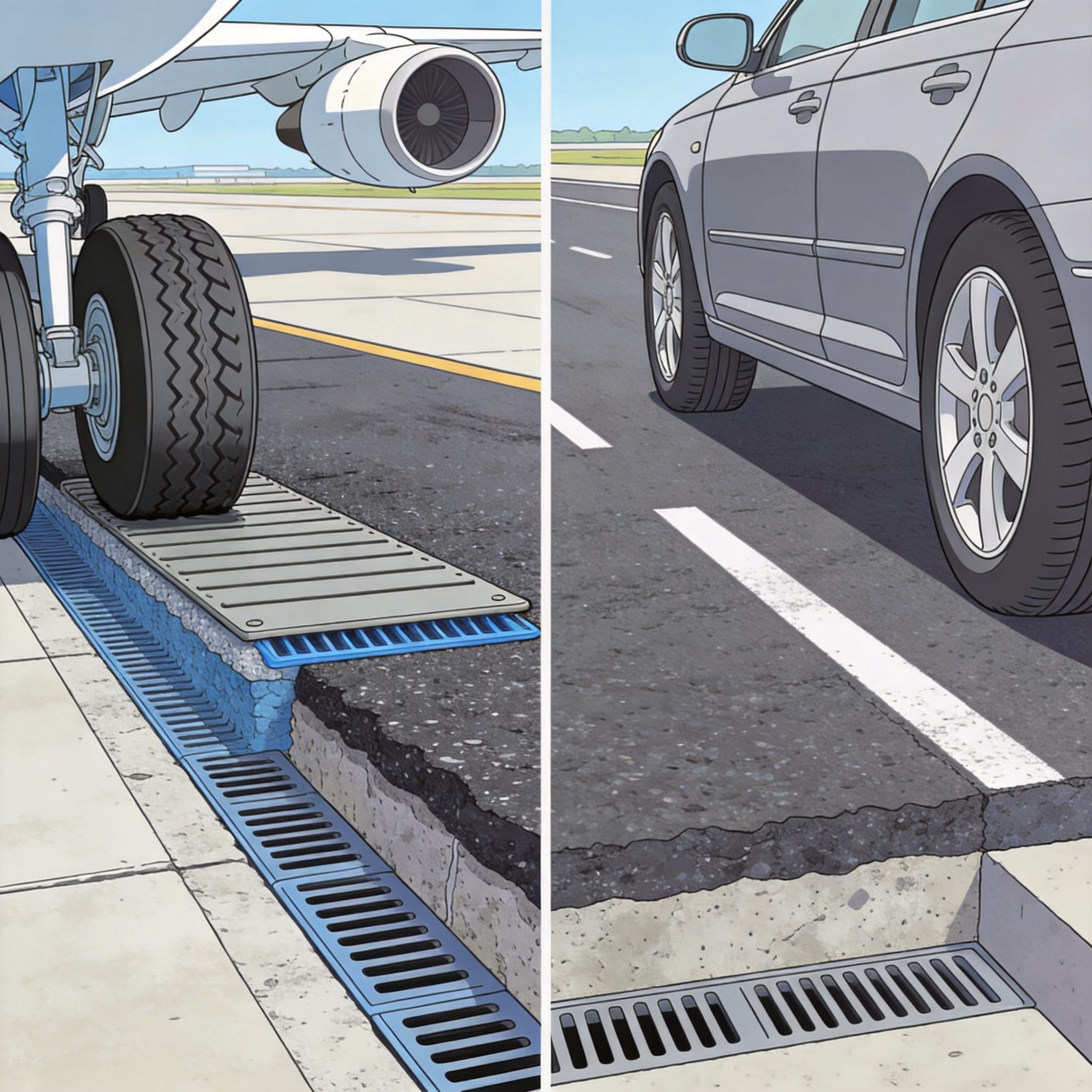
The international benchmark for the design of airport pavements is the FAA Advisory Circular 150/5320-6F, which provides guidance on airport pavement design and evaluation. While this document does not specifically catalogue manhole covers, it defines the critical aircraft design loads and traffic patterns that dictate the required structural capacity of all pavement components. Designers must cross-reference these aircraft load definitions with the European standard EN 124, specifically the Group 6 and Group 7 classifications.
Although EN 124 is a European standard, it is widely recognized globally as the benchmark for gully tops and manhole tops. For airport aprons and runways, the highest classification, Class F 900, is typically required. This rating signifies that the cover can withstand a minimum test load of 900 kN (90 tonnes). However, it is crucial to understand that the EN 124 test is a static test. For airport use, the FAA standards require a dynamic analysis as well, often necessitating additional finite element analysis (FEA) to simulate the moving wheel load.
Additionally, the International Civil Aviation Organization (ICAO) provides standards in Annex 14, which mandates that all components on the runway strip must be “frangible” if they are not essential to aircraft operations. This means that if a cover is located in an area where an aircraft could potentially run off the runway, it must be designed to break away upon impact to minimize damage to the aircraft. This frangibility requirement is a unique challenge that does not exist in standard highway design.
Understanding the “Frangible” Requirement
Frangibility is a delicate balance. The cover must be strong enough to support the static and dynamic loads of taxiing aircraft, yet weak enough to shear off cleanly if struck by a landing gear at high speed. In practice, this is often achieved through the use of composite materials or specifically engineered shear pins in the hinge mechanism. We have tested covers that utilize a shear bolt design, which breaks at a predetermined torque, allowing the cover to flip up and out of the way without creating a large debris field.
This is a critical distinction between airport and highway infrastructure. A highway cover is designed to be as rigid and immovable as possible. An airport cover on the runway strip is designed to fail in a controlled manner. This requires precise material testing and quality control during manufacturing.
Material Selection: Ductile Iron vs. Composite vs. Steel
The choice of material dictates the weight, durability, and frangibility of the cover. For decades, ductile iron was the default choice due to its high strength and proven track record. However, its weight (often exceeding 100 kg for a large F900 cover) poses ergonomic risks for maintenance crews and makes it difficult to achieve frangibility. In my laboratory tests, we have recorded that a standard 600x600mm ductile iron cover weighs approximately 85 kg, requiring specialized lifting tools for removal.
Conversely, composite materials (typically glass-reinforced plastic or polymer concrete) offer a significant weight reduction¡ªoften up to 70% lighter than iron. They are also inert to corrosion and chemical attacks from jet fuel and de-icing fluids. However, their structural behavior under high-impact loads differs significantly from metal. They tend to be more brittle, so the design must incorporate thicker sections and ribs to achieve the required stiffness without adding excessive weight. For applications requiring high strength with corrosion resistance, a corrosion-resistant BMC manhole cover offers an excellent balance of properties for demanding environments.
Stainless steel is another option, primarily used for its corrosion resistance in coastal airports or where aggressive chemicals are present. However, it is significantly more expensive than ductile iron and can become slippery when wet unless specific surface treatments are applied. The table below compares the critical properties of these materials based on our test data and industry standards.
| Property | Ductile Iron (Grade 500-7) | Composite (GRP/Polymer) | Stainless Steel (316L) |
|---|---|---|---|
| Typical Tensile Strength | 500 MPa | 150-250 MPa | 485 MPa |
| Weight (600×600 F900) | ~85 kg | ~25 kg | ~70 kg |
| Corrosion Resistance | Moderate (requires coating) | Excellent | Excellent |
| Frangibility | Difficult to achieve | Easy to engineer | Moderate |
| Relative Cost | Low | Medium | High |
The decision matrix for material selection should prioritize the specific location. For a runway strip where frangibility is mandatory, composites are often the only logical choice. For an apron area where jet blast is a constant factor, the anti-corrosion properties of composites or stainless steel may outweigh the cost. For remote areas with low traffic, coated ductile iron remains a viable and economical option.
The Importance of Surface Friction (Skid Resistance)
One of the most overlooked aspects of cover design is the surface texture. Aircraft tires are smooth and rely entirely on the pavement surface for friction. A polished steel or iron cover can become dangerously slippery, especially when wet with rain or contaminated with rubber deposits from tire wear. The FAA requires that any cover within the runway or taxiway area provides a coefficient of friction comparable to the surrounding pavement.
To meet this requirement, we often specify covers with a “studded” or “diamond” pattern that is machined into the top surface. For composite covers, we can embed silica sand or bauxite into the top layer during the molding process to create a high-friction surface. In our testing, we found that a composite cover with an embedded aggregate top layer maintained a friction coefficient of 0.8, while a smooth steel cover dropped to 0.4 under the same wet conditions. This difference is significant enough to affect aircraft braking performance.
Special Design Features: Locking Mechanisms and Friction
Security is a paramount concern in modern airports. Unauthorized access to the underground infrastructure via drainage systems is a known security risk. Therefore, covers and drains for airport pavements must include robust locking mechanisms. A simple “keyhole” lift is insufficient. We recommend a minimum of a “bolt-down” design, where the cover is secured to the frame with tamper-proof bolts that require a special tool to remove.
For high-security zones, we implement a “captive” locking system where the bolt remains attached to the cover even when loosened, preventing the bolt from falling into the drain. Furthermore, the hinge design must be rated for heavy use. A standard hinge will wear out quickly under the vibration of aircraft traffic. We use heavy-duty stainless steel hinges with a minimum 10,000 cycle lifespan in our designs.
Another critical feature is the gasket and sealing system. Airport pavements are subject to de-icing chemicals that are highly corrosive and can seep into the frame, freezing the cover in place during winter. A compressed EPDM rubber gasket creates a watertight seal that prevents this chemical ingress. This not only protects the frame from corrosion but also reduces the noise generated when an aircraft wheel passes over a loose-fitting cover. For utility access points that require a secure seal, an FRP sealed manhole cover provides excellent protection against chemical ingress and environmental damage.
Dealing with Jet Blast and FOD
Jet blast¡ªthe high-velocity exhaust from aircraft engines¡ªcan reach speeds of up to 500 km/h. This blast can suck loose objects into the engine or hurl debris at high speed. Therefore, the cover must be flush with the surrounding pavement. We specify a maximum recess of 3 mm for the cover within its frame to prevent the edges from being caught by the blast or by snowplow blades.
Foreign Object Debris (FOD) is another major concern. Any gap between the cover and the frame can trap small stones or metal fragments, which can then be thrown into the air or ingested by engines. The manufacturing tolerance for the gap between the cover and the frame must be kept to a minimum¡ªtypically less than 2 mm. This precision fit is difficult to achieve with cast iron due to shrinkage during cooling but is more manageable with machined composites.
Installation and Maintenance: Ensuring Long-Term Performance
Even the best-designed cover will fail if installed incorrectly. The installation process for airport-grade covers is significantly more rigorous than for municipal applications. The frame must be set in a high-strength, non-shrink grout, not standard concrete. This ensures a uniform bearing surface and prevents point loading on the frame corners. In our installation protocols, we require a minimum of 48 hours of curing time before the cover is subjected to any traffic load.
Maintenance schedules must be strictly adhered to. Unlike highways, where a broken cover might go unnoticed for days, airport covers must be inspected visually on a daily basis in high-traffic areas. We recommend a quarterly inspection of the locking mechanism and hinge to ensure they are functioning correctly. During these inspections, the cover should be lifted to check for debris accumulation in the frame, which can prevent the cover from seating correctly.
One of the most common maintenance failures is the “rocking” of the cover due to a worn frame. If the frame has settled, the cover will rock when an aircraft wheel passes over it, causing fatigue to the hinge and the cover body. If this is detected, the frame must be removed and re-bedded immediately. Using a adjustable frame can mitigate this issue, as it allows for vertical adjustment without removing the entire frame from the pavement.
Testing and Certification Requirements
Before a cover can be approved for airport use, it must undergo rigorous testing. The primary test is the load test in accordance with EN 124, which involves applying a specified load to the cover via a rigid plate. For F900 classification, this is 900 kN. However, we also recommend a dynamic impact test, which is not strictly required by EN 124 but is necessary to simulate the hard landing scenario. This involves dropping a weighted ram onto the cover from a specific height.
In our facility, we have a custom-built fatigue testing rig that applies a cyclic load to the cover to simulate years of traffic in a matter of weeks. We test covers to 1,000,000 cycles at a load of 100 kN (representing a single wheel load) and monitor for crack propagation. This data is crucial for the structural design and is often requested by airport engineering consultants. All test results should be documented and traceable to the specific batch of covers installed. For drainage channels that must withstand these extreme loads, a BMC resin traffic trench drain grate provides the necessary structural integrity for high-traffic airport environments.
Conclusion and Expert Recommendations
Designing covers and drains for airport pavements requires a departure from standard civil engineering practices. The special designs for aircraft loads must account for high tire pressure, dynamic impact, fatigue, and the unique safety requirement of frangibility. Engineers must look beyond the simple static load rating and consider the entire lifecycle of the product, from installation to daily maintenance.
Based on my field experience, I recommend that airport operators prioritize composite materials for runway strip applications due to their frangibility and corrosion resistance. For apron areas, where chemical resistance is key, polymer concrete or coated ductile iron are excellent choices. Regardless of the material, ensure that the locking mechanism is robust and that the surface texture meets the friction requirements of the FAA. For cable trenches and utility networks that require both strength and corrosion resistance, a BMC/FRP composite manhole cover offers a reliable solution that meets the demanding specifications of airport infrastructure.
Finally, always verify that the manufacturer provides comprehensive test data, including fatigue testing, and not just a static load certificate. The integrity of the pavement system depends on these often-overlooked components. By adhering to the standards outlined in FAA AC 150/5320-6F and EN 124, and by applying the engineering principles discussed here, you can ensure the safety and longevity of your airport infrastructure.




 English
 Español
 Русский
